Design a Counter That Counts in the Following Sequence
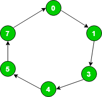
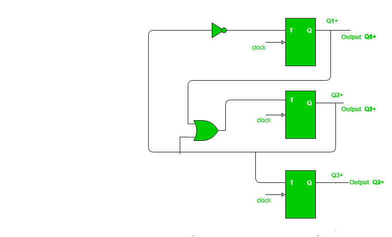
Explanation For given sequence state transition diagram as following below. 0 1 3 4 5 7 0 using T flip-flop.

Eee 120 Quiz 5 Eee Quiz Tutorial
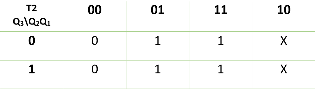
Table2 shows the circuit excitation table.
. Write the excitation table and circuit excitation table Table1 shows the excitation table for JK flip flop. These values will be displayed on a seven-segment display like the one used in Lab 3. Let us choose JK flip-flops to design the counter.
This modulus six counter requires three SR flip-flops for the design. 943 Design of a Synchronous Modulus-Six Counter Using SR Flip-Flop The modulus six counter will count 0 2 3 6 5 and 1 and repeat the sequence. Using JK flip flop.
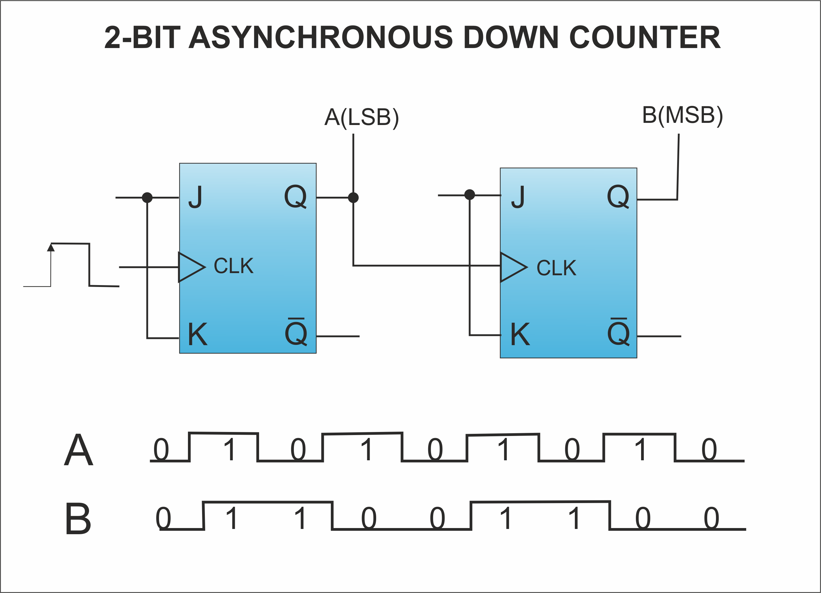
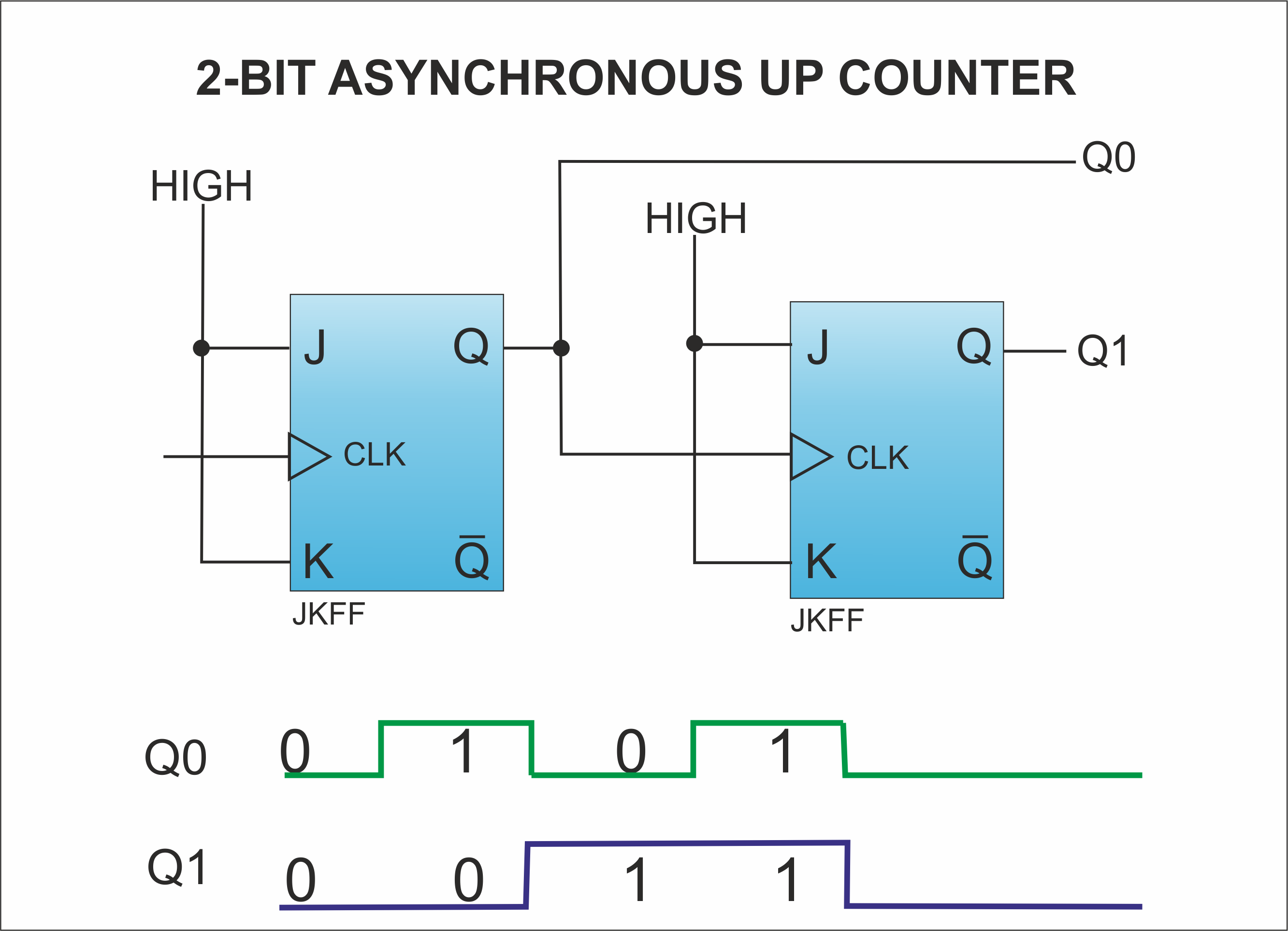
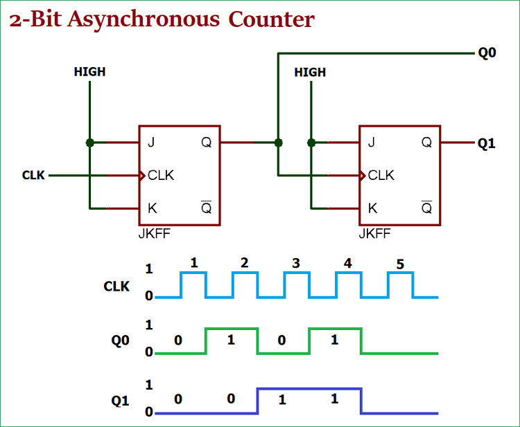
Connect J and K inputs to logical 1. This is a constant logical 0. Note how the least significant bit LSB toggles between 0 and 1 for every step in the count sequence while each succeeding bit toggles at one-half the frequency of the one before it.
To design a counter which count in the following sequence 763501 by using SR- FF the input of SR-FFs are. 011 we have to use three T flip flops. Show that when binary states 010 an.
1a using JK flip flops. 1c using D flip flops. As we have to construct Mod-6 counter ie N 6.
You dont use the 1 bit. Since the highest state is 6 ie. Number of flip flops.
Thus Number of flipflops required 3. Let the type of flip-flops be RS flip-flops. Write the excitation table.
Choose the type of flip flop. Design A Counter That Counts In The Following Sequence. Draw state diagram for the counter.
As N6 then n3. Use a two bit counter. Design a counter that counts in the following sequence It is less complicated than uncomplicated to create exceptional nail artwork for short nailsAll you must do would be to introduce some glitter in.
Design a counter with the following repeated binary sequence. EXCITATION TABLE VIDEO LINK. Electrical Engineering questions and answers.
What will the counter hardware look like if the unused states are to be considered as dont cares. Written 52 years ago by akamitkhareak 370. Use JK flip-flops given to you at the start of the semester.
In this video the step by step method to design a synchronous counter which gives the sequence 0011220011is given. If we examine a four-bit binary count sequence from 0000 to 1111 a definite pattern will be evident in the oscillations of the bits between 0 and 1. Since it is a 3-bit counter the number of flip-flops required is three.
Design a counter that counts the following sequence of 2-3-1-0 and repeat. 0 1 3 7 6 4. The given count sequence has 3 bits and there are 6 seven states.
0100 0000 0010 0110 0111 0011 0101 0001 1100 1111 1110 1010 1011 1101 1000 1001 after that it goes back to 0100 a Make the next state table for this counter b Design a digital circuit using D flip flops and minimum circuit components. Connect the two Q terminals to outputs 1 and 2. 2 n N.
Determine the desired number of FFs From the given sequence the number of FFs is equal to 3. 1b using T flip flops. 0 4 2 1 6.
Find the number of flip flops for the required MOD counter. Problem Design synchronous counter for sequence. Design a synchronous counter that counts as 000 010 101 110 000 010 Ensure that the unused states of 001 011 100 and 111 go to 000 on the next clock pulse.
The state table is as shown in Table 31. Hence the counter to be designed will have 3 flip-flops. Let the three flip-flops be A B and C.
Table1 shows the excitation table for T flip flop. Modify your design in question 1a so that the circuit works according to the following function table. Number of flipflops required can be caluculated for minimum value of n which satisfies the below equation.
Design a counter that counts the following sequence. Design a counter which counts 0 4 8 2 6 and repeats using. Draw the state diagram.
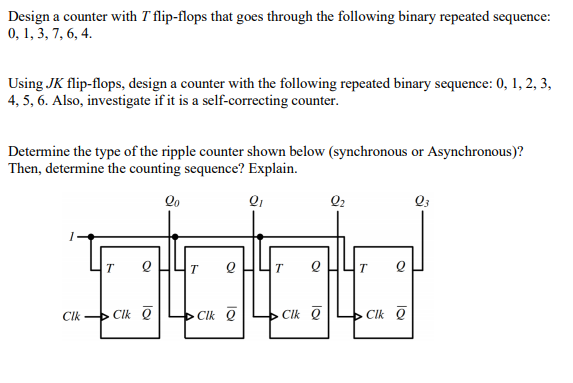
The truth table of a modulus six. Design a counter with T flipflops that goes through the following binary repeated se- quence. The count sequence is 7-3-1-2-5-4-6.
Connect Q1 to clock 2. This video is the first of three videos showing how to design a counter with an arbitrary sequence using JK flip flops. How do you design a three-bit counter that counts in the sequence 0 2 4 6 0.
Connect the clock input to Clock 1. The most significant bit MSB only.
How To Design A Synchronous Counter That Counts The Sequence 0 2 4 6 8 10 12 11 9 7 5 3 1 0 2 And Uses Jk Sr T And D Flip Flop For Each Bit Quora
Counters Circuitverse
Design Counter For Given Sequence Geeksforgeeks

Experiment Write Vhdl Code For Realize All Logic Gates In 2021 Logic Experiments Writing

Pin On Led Circuits

When Do We Use Continual And Continuous Writing Lessons Adjective Meaning Grammar Rules

Synchronous Counter And The 4 Bit Synchronous Counter
Design Counter For Given Sequence Geeksforgeeks
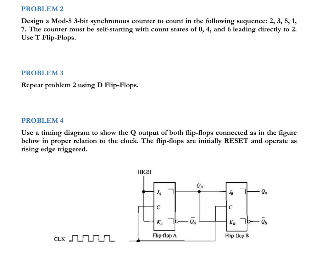
Solved Problem 2 Design A Mod 5 3 Bit Synchronous Counter To Chegg Com
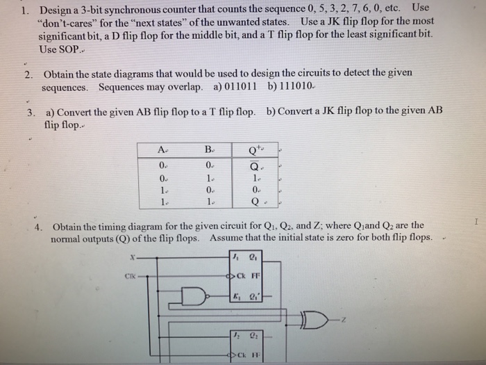
Solved Design A 3 Bit Synchronous Counter That Counts The Chegg Com
Design Counter For Given Sequence Geeksforgeeks

Bidirectional Counter Up Down Binary Counter

Plc Counter Logic Example Ladder Logic Basic Electrical Engineering Plc Programming

Tutorial 1 Binary Counter Fpga Implementation Binary Counter Tutorial

Free Standing Led Circuit Led S And Resistors In 2020 Electronics Projects Diy Diy Electronics Electronics Projects
How To Design A Three Bit Counter That Counts In The Sequence 0 2 4 6 0 Using Jk Flip Flop Quora
Asynchronous Counter Definition Working Truth Table Design
Solved Design A Counter With T Flip Flops That Goes Through Chegg Com
Counters Circuitverse


Comments
Post a Comment